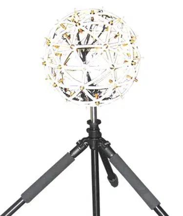
Sound power measurement with MF710 / MF720. They are hemispherical arrays developed by BSWA for sound power measurement.
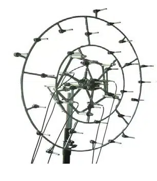
MF710 meets the requirements of the 10-microphone method according to GB 6882 1986, ISO 3745:1977, GB/T 18313 2001 and ISO 7779:2010.
MF720 meets the requirements of the 20-microphone method according to GB/T 6882-2008 and ISO 3745:2012.
The MF710 / MF720 was developed as a small, lightweight and easy-to-mount bracket.
Microphones can be mounted on the hemispherical surface very quickly and accurately, making it very easy to comply with the standard requirements for sound power measurement.
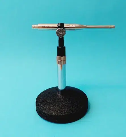
Microphone holder for sound power measurement Radius 1m
Meet the requirement of 10 microphone method according to GB 6882-1986, ISO 3745:1977, GB/T 18313-2001 and ISO 7779:2010.
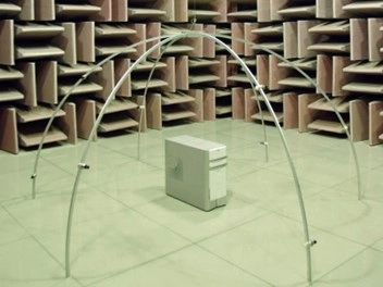
The acoustic array measurement system, commonly known as the acoustic camera, is composed of multiple microphones arranged according to a certain rule, and the sound pressure level distribution on a plane or spherical surface is generated by the array signal processing algorithm (such as beam-forming, acoustic holography).
The sound visualization is realized by means of graphs, and the noise source distribution of the measured object is displayed by means of photos or videos.
Acoustic array system is widely used in noise source location, wind tunnel noise testing and machine condition monitoring.
Acoustic array systems usually require dozens, or even hundreds of microphones.
BSWA provides high-performance, economical array microphones for the research and development of acoustic array systems.
Let’s talk about how to choose the right microphone for your array.
Key points for choosing the array microphone
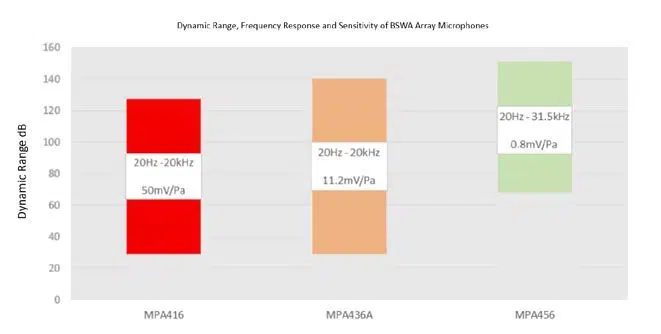
1, Dynamic Range
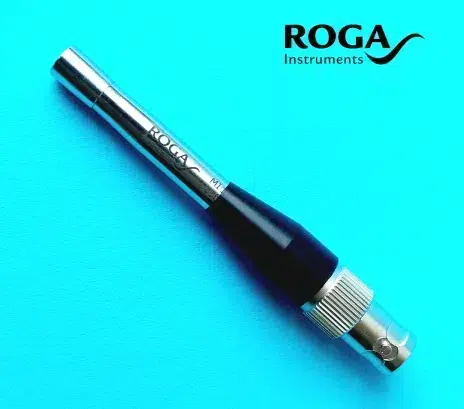
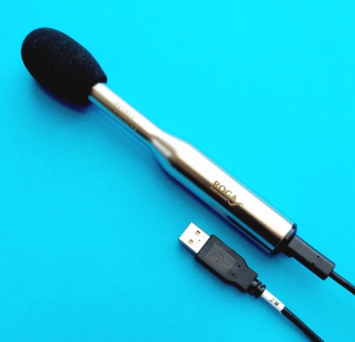
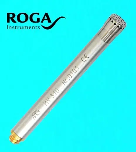
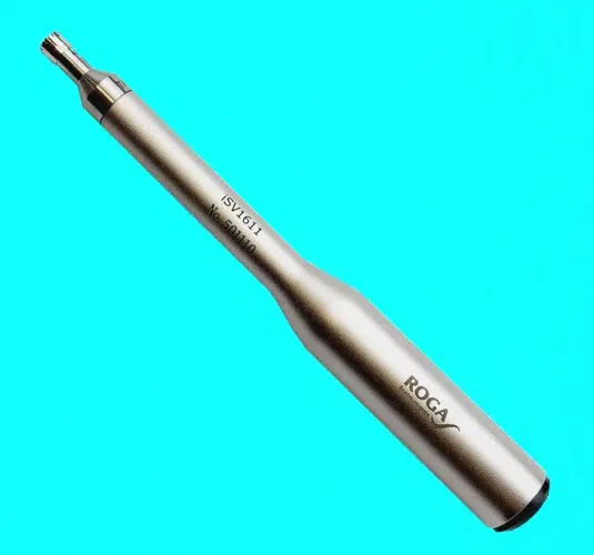
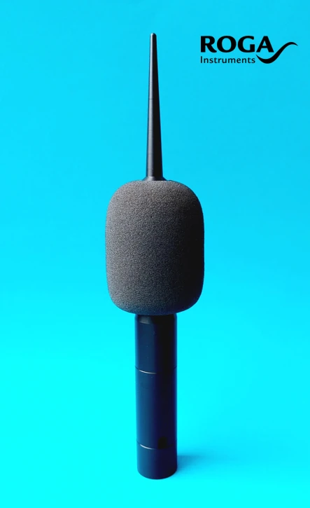
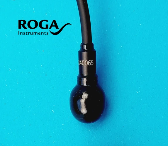
ROGA has three array microphones, RG-50, MPA416, MPA436A and MPA456, which cover the measurement range from 29dBA to 151dB. However, the sound pressure measurement range of each model is different, customers will need to choose the appropriate model according to the applications.
For example, RG-50 & MPA416 is suitable for conventional acoustic array testing.
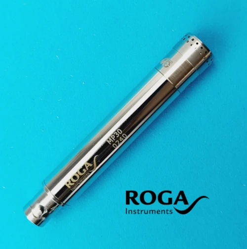
MPA436A is suitable for high dynamic range acoustic testing, MPA456 is an array microphone designed for high sound pressure and acoustic wind tunnel.
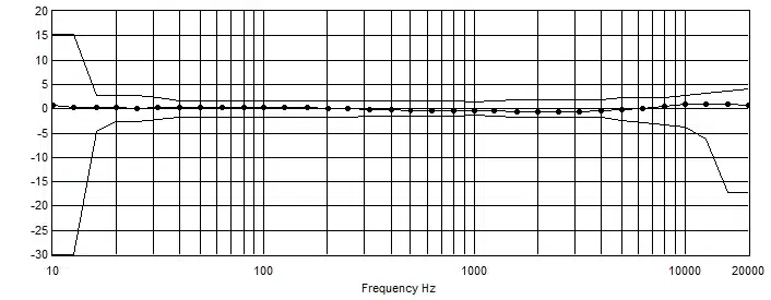
RG-50 Frequency Response
2, Frequency Response
The MI17, MPA416 and MPA436A have the frequency range from 20 Hz to 20 kHz.
They are suitable for the most applications in noise measurements. The MPA456 has good performance in high frequencies up to 32 kHz.
It is suitable for conditioning monitoring using acoustic array technologies.
3, Phase matching
The phase difference between the microphones are required to be small enough to ensure the accuracy of measurements.
Regardless of the algorithm or the array shape, all calculations and delays are based on the premise that the microphone time differences are highly consistent.
That is, the phases are highly consistent.
ROGA array microphones are strictly phase matched before ex-factory inspection, and the phase difference of a batch of microphones is controlled within ±5 degrees up to 5000 Hz.
We use cookies to ensure that we give you the best experience on our website. If you continue to use this site we will assume that you are happy with it.