FFT Analysis in Vibration - NVH Software - NVH Analyzer Software
FFT analyzer software for sound and vibration measurements
NVH analysis - Modal analysis - Order analysis - Acoustic analysis - Operational deflection shape analysis
NVH Analysis with NVH Analyzer Pro data acquisition software is the solution for simultaneously acquiring and displaying signals from different sources and saving them in a file.
With the post-processing function, all powerful math and analysis functions can also be applied to the already saved data.
NVH Analyzer Software DAQ Hardware
Bump Test Vibration – Impact Hammer Test
Operating deflection shape analysis with impulse hammer and raw data recording
Operating Deflection Shapes (ODS) analysis software can be used individually or in conjunction with other applications.
The software features tailored workflows and include all the necessary functionality for conducting ODS measurement and analysis, such as time, spectral and run-up/down.
This short presentation demonstrates the recording of nine IEPE accelerometers mounted on a steel plate.
The steel plate is excited by an impulse hammer in order to generate raw data for an operational vibration analysis.
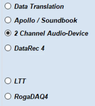
DAQ INPUTS
ROTOR DYNAMICS
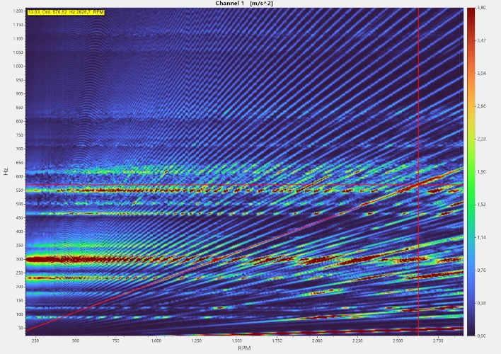
ORDER ANALYSIS

NVH Analyzer Pro compatible measurement data acquisition
With a focus on powerful ROGA and ASIO compatible hardware from the professional studio world, the introduction of the innovative NVH Analyzer Pro software results in improved, intuitive usability, shortened setup times and fewer setup errors.
This allows measurements to be repeated, easily saving you time and money.
USER INTERFACE
Choose the right measurement method for your application.
- Impulse hammer testing FRF measurement
- FFT Vibration – order analysis and acoustics
- Dual Plane Balancing
- Monitoring Measurement
RECORDING
NVH-IMP | NVH-FFT | NVH-ODS Analysis Software Function Overview
REALTIME DATA PROCESSING | GRAPHICS AND VISUALISATION |
|---|---|
User interface | Configurable graph screens |
Time domain | Recorder (1 to 16 Ch, real-time autoscaling) Scope (trigger, persistence, envelope), Analog/digital meter, tabular display, overload indicator |
Multi domain | XY recorder (Lissajous), 2D graph, Orbit graph FRF plot (amplitude/phase/real/imaginary vs frequency) |
Application specific | FRF geometry, Modal circle, Rotor balancer, Harmonic FFT, Vector scope Auto-generating of displays with typical application setup |
DATA IMPORT | ASCII *.txt WAV *.wav MP3 *.mp3 Stiegele Datasystems MicroEdition, *.mdf TEAC TAFFmat Format, *.hdr, *.dat |
DATA EXPORT | ASCII *.txt Excel *.csv |
FILTERING | |
IIR | Low pass/high pass/band pass/ 2nd to 6th order, Butterworth |
STATISTICS | |
Calculation base | Time based |
Types | RMS, Average, Peak-Peak |
Data range | Running, Triggered, Start-Stop |
REFERENCE CURVES | |
Types | time, value, dual-value, vector, XY, frequency domain with interpolation |
TIME DOMAIN | ANALYSIS |
Integration/Derivation | single/double with adjustable filter, automatic unit conversion (e.g. acceleration to velocity to displacement) FFT |
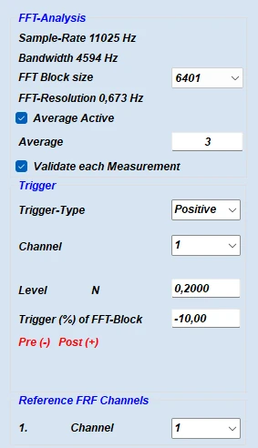
FFT ANALYSER | |
General | multiple independent FFT analyzers at the same time |
Amplitude types | amplitude FFT (Ampl, RMS, Power, PSD, RMS SD), Complex FFT (Real/Imag/Ampl/Phase) |
Windowing | Hanning / Hamming |
Window overlap | 0, 10, 25, 50, 66, 75, 90 % |
Triggered FFT | triggered time-range with pre- and post-trigger as input, auto calculation of window resolution, averaging of triggered FFT‘s, e.g. for bump – impulse hammer test application |
DC cut off | 0,5 Hz |
FFT block size | 26, 51, 101, 201, 401, 801, 1601, 3201, 6401, 12801, 25601 |
Acoustic weighting | A, B, C, Lin (Z) |
Octave | 1/3, type; Lin/A/B/C weighting, Lin/Pk avg with overlap |
Visualization | amplitude axis with real-time autoscaling: Lin/log/0dB/reference dB/Sound(A) |
Post processing | possible to add/change all calculations offline on the stored raw data |
Spectrum markers | Free |
ORDER TRACKING | |
Frequency source | Counter: optical tacho, proximity, pick-up probe (1 pulse/rev), optical strip tape probe (with bl/wh tape, algorithm for determining number of pulses), 1-, 2-, 3- tracks encoder, gear tooth with missing teeth (e.g. 60-2), CDM, CDM with zero RPM channel: any analog speed channel, virtual (synthesized RPM channel, also in post-processing) Analog pulses: analog signal (e.g. 60-2) / analog tacho + angle sensor math |
Input Ch. for analysis | any analog input channel, e.g. IEPE accelerometer, microphone, etc… |
Visualization | 3D graph, Order and Frequency spectrum, Waterfall FFT real time extraction of single spectral lines of matrix Orbit plot, XY recorder, Bode plot, Nyquist plot of any order, any signal vs RPM |
Calculation criteria | Runup / Coast down / Both directions with RPM limits and Delta RPM and/or Delta Time |
Order FFT | from 8 to 256 orders, resolution from 1 to 1/64 |
Harmonics | extract overall RMS and amplitudes/phases/Real/Imag of selectable orders (from sub-orders e.g. 0.1x, 1x, 2x, 3x to max order) in Time domain & RPM domain |
Post processing | possible to add/change all calculations offline on the stored raw data |
Data export | Complex data (Real/Imag/Ampl/Phase) in any format, see Software Export section |
TORSIONAL VIBRATION | |
General | high precision rotational and torsional vibration and slippage measurement, by use of 2 rotary encoders |
Frequency source | optical strip tape probe (with bl/wh tape, algorithm for determining number of pulses), 1-, 2-, 3- tracks encoder, gear tooth with missing teeth (e.g. 60-2), CDM, CDM with zero |
Angle accuracy | up to 0,00075° at 10 000 rpm |
Angle resolution | up to 0,06° at 10 000 rpm |
Features | Rotational DC filter (0,1 to 10 Hz), compensation of uncentered encoder mounting |
Output | Rotational angle/velocity, Torsional angle/velocity |
Visualization | angle based view, time domain |
MODAL TEST | |
Impact hammer method | roving hammer/roving accelerometer moving through points, averaging of multiple hits, double hit rejection, rejecting of hits (action buttons), grouping of sensors, adjustable excitation, and response window |
Free-run mode | Function generator (Apollo Series) for shaker excitation (swept sine, burst, chirp…) Hanning/Hamming windowing with overlap 0, 25, 50, 66, 75 % operating deflection shapes (Spectral ODS) |
FRF | Receptance, Effective Mass, Mobility, Impedance, Dynamic Compliance, Dynamic Stiffness, Transmissibility |
Modal Parameters | Mode Indicator Function (MIF), extract exact frequencies and damping factors with Modal circle fit (Option) |
Post processing | FRF from stored raw data, in free-run mode |
Geometry | Geometry editor, load, save, import models in UFF (UNV) format (Option) |
Animation | movement of nodes for selected frequency (place marker), change speed and amplitude (Option) |
Data export | Complex data (Real/Imag/Ampl/Phase) in UFF (UNV) format or any other, see Software Export section |
HUMAN BODY VIBRATION | |
General | module for judging vibration levels for risk of damage to the human body |
Supported types | Hand arm |
Compliance | to ISO 8041, ISO 2631-1, ISO 2631-5, ISO 5349 standards |
SOUND LEVEL | |
Frequency weighting | A, B, C, Lin (Z) |
Time weighting | Fast, Slow, Impulse |
Octave plot | 1/3 Lin/A/B/C/ weighting, Lin/Pk avg with overlap |
Supported standards | IEC 60651, IEC 60804, IEC 61672 |
Outputs | Sound pressure level, any combination of Frequency and Time weighting, Leq, Lpk, Lim, LE overall or on custom statistical rate, percentile levels (1, 5, 10, 50, 90, 95, 99 %) |
More features | real-time narrow band FFT, frequency weighted raw channel |
Calibration | auto-calibration of scaling factor with reference calibrator (1kHz, 94dB, 114 dB acc to IEC 60942:2003) |
BALANCING | |
Application | for rigid rotor running below its resonance frequency, based on order tracking (amplitude & phase), single- and dual-plane |
Supported tacho inputs | Counter: optical tacho, proximity, pick-up probe (1 pulse/rev), optical strip tape probe (with bl/wh tape, algorithm for determining number of pulses), 1-, 2-, 3- tracks encoder, gear tooth with missing teeth (e.g. 60-2), CDM, CDM with zero RPM channel: any analog speed channel, virtual (synthesized RPM channel, also in post-processing) Analog pulses: analog signal (e.g. 60-2) / analog tacho + angle sensor math alarm output if velocity exceeds predefined value weight splitting |
Visualization | Vector polar plots of 1st order of all runs |
Sequence | step-by-step guidance through procedure: initial run, trial mass run, correction mass run, repeat steps if needed |
Features | x and y direction balancing at the same time, when using triaxial sensor |
SOUNDPOWER | |
Standards | ISO 3741 (noise source in reverberation test room), ISO 3744 (engineering grade, free field over reflective plane), ISO 3745 (precision grade, anechoic or hemi anechoic room) |
Geometries | Parallelepiped, Cylindric, Hemisphere, Sphere |
Microphones | 10 number of microphones; positions will be calculated according to entered geometry and size, floor / 1 wall / 2 wall setup |
Measurement | Guided sequence, previous/next group (action buttons), background noise/sound measurement, with repeatability check, minimum measurement duration & level plausibility check and warnings, grouping of microphones |
Octave | 1/3 octave |
Correction methods | C1 and C2 meteorological, K1 background noise and, K2 room noise (mean absorption grade, reverberation time, K2 editor) |