FRF Modal Analysis - Bump Test Vibration - Natural Frequency
bump test generator - bump test endwinding - bump test rotor - bump test machine - bump test motor
Impulse Hammer - Impact Hammer - Vibration Testing
ROGA Instruments offers a complete system for the following measurement tasks: Impact hammer tesing of large and heavy structures bump test generator, bump test vibration, rotor dynamics and resonance analysis.
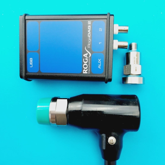
All necessary components are included in the DAQ2-BUMP-SET as follows. Impulse hammer, accelerometer, RogaDAQ2, sensor cable 2 meters long, NVH-IMP and NVH-FFT software.
Our software enables you to perform state-of-the-art analyses of your systems using techniques such as the impulse hammer test, Operational Vibration Analysis and Experimental Modal Analysis.
Our NVH Analyser Pro is designed to be user-friendly, with intuitive user interfaces and powerful analysis algorithms. Whether you are a researcher, engineer or technician, this software will enable you to better understand your systems and improve their performance.
Impact Hammer Test Set
DAQ2-BUMP-SET
- Scope of delivery:
- RogaDAQ2-SET
- IH-20 Impulse Hammer
- KS84.100 Accelerometer with 208 magnet mount base
Analog Input | 2ch single ended BNC, IEPE, AC, DC |
|---|---|
Simultaneously sampling ADCs | 2 |
ADC Resolution | 24 Bit |
Sampling rate | 48 kHz |
Ch. 1 Range input Ch. 2 Range input | ±5 Volt for Impact Hammer ±5 Volt for IEPE Accelerometer |
AC- or DC-coupling | Selectable |
IEPE sensor supply | 4 mA – 24 Volt |
Anti-Aliasing filter | Self adjusting |
Accuracy | better ± 0,1 dB |
Dynamic Range | 124 dB(FFT-based) |
THD | < 0,005%, |
Frequency Response | DC – 24 kHz (± 0,05 dB)
|
With IEPE Supply |
0.3 – 24 kHz (± 0,05 dB) |
Powered by USB Port | Power consumption < 1W |
Temperature range | 0 to + 50 °C |
Dimensions | 85 (w) x 132 (d) x 35 (h) mm |
Weight | 230 g |
Imulse Hammer Test Presentation
NVH-IMP | NVH-FFT | NVH-ODS Function Overview
REALTIME DATA PROCESSING | GRAPHICS AND VISUALISATION |
|---|---|
User interface | Configurable graph screens |
Time domain | Recorder (1 to 16 Ch, real-time autoscaling) Scope (trigger, persistence, envelope), Analog/digital meter, tabular display, overload indicator |
Multi domain | XY recorder (Lissajous), 2D graph, Orbit graph FRF plot (amplitude/phase/real/imaginary vs frequency) |
Application specific | FRF geometry, Modal circle, Rotor balancer, Harmonic FFT, Vector scope Auto-generating of displays with typical application setup |
DATA IMPORT | ASCII *.txt WAV *.wav MP3 *.mp3 Stiegele Datasystems MicroEdition, *.mdf TEAC TAFFmat Format, *.hdr, *.dat |
DATA EXPORT | ASCII *.txt Excel *.csv |
FILTERING | |
IIR | Low pass/high pass/band pass/ 2nd to 6th order, Butterworth |
STATISTICS | |
Calculation base | Time based |
Types | RMS, Average, Peak-Peak |
Data range | Running, Triggered, Start-Stop |
REFERENCE CURVES | |
Types | time, value, dual-value, vector, XY, frequency domain with interpolation |
TIME DOMAIN | ANALYSIS |
Integration/Derivation | single/double with adjustable filter, automatic unit conversion (e.g. acceleration to velocity to displacement) FFT |
FFT ANALYSER | |
General | multiple independent FFT analyzers at the same time |
Amplitude types | amplitude FFT (Ampl, RMS, Power, PSD, RMS SD), Complex FFT (Real/Imag/Ampl/Phase) |
Windowing | Hanning / Hamming |
Window overlap | 0, 10, 25, 50, 66, 75, 90 % |
Triggered FFT | triggered time-range with pre- and post-trigger as input, auto calculation of window resolution, averaging of triggered FFT‘s, e.g. for bump – impulse hammer test application |
DC cut off | 0,5 Hz |
FFT block size | 26, 51, 101, 201, 401, 801, 1601, 3201, 6401, 12801, 25601 |
Acoustic weighting | A, B, C, Lin (Z) |
Octave | 1/3, type; Lin/A/B/C weighting, Lin/Pk avg with overlap |
Visualization | amplitude axis with real-time autoscaling: Lin/log/0dB/reference dB/Sound(A) |
Post processing | possible to add/change all calculations offline on the stored raw data |
Spectrum markers | Free |
ORDER TRACKING | |
Frequency source | Counter: optical tacho, proximity, pick-up probe (1 pulse/rev), optical strip tape probe (with bl/wh tape, algorithm for determining number of pulses), 1-, 2-, 3- tracks encoder, gear tooth with missing teeth (e.g. 60-2), CDM, CDM with zero RPM channel: any analog speed channel, virtual (synthesized RPM channel, also in post-processing) Analog pulses: analog signal (e.g. 60-2) / analog tacho + angle sensor math |
Input Ch. for analysis | any analog input channel, e.g. IEPE accelerometer, microphone, etc… |
Visualization | 3D graph, Order and Frequency spectrum, Waterfall FFT real time extraction of single spectral lines of matrix Orbit plot, XY recorder, Bode plot, Nyquist plot of any order, any signal vs RPM |
Calculation criteria | Runup / Coast down / Both directions with RPM limits and Delta RPM and/or Delta Time |
Order FFT | from 8 to 256 orders, resolution from 1 to 1/64 |
Harmonics | extract overall RMS and amplitudes/phases/Real/Imag of selectable orders (from sub-orders e.g. 0.1x, 1x, 2x, 3x to max order) in Time domain & RPM domain |
Post processing | possible to add/change all calculations offline on the stored raw data |
Data export | Complex data (Real/Imag/Ampl/Phase) in any format, see Software Export section |
TORSIONAL VIBRATION | |
General | high precision rotational and torsional vibration and slippage measurement, by use of 2 rotary encoders |
Frequency source | optical strip tape probe (with bl/wh tape, algorithm for determining number of pulses), 1-, 2-, 3- tracks encoder, gear tooth with missing teeth (e.g. 60-2), CDM, CDM with zero |
Angle accuracy | up to 0,00075° at 10 000 rpm |
Angle resolution | up to 0,06° at 10 000 rpm |
Features | Rotational DC filter (0,1 to 10 Hz), compensation of uncentered encoder mounting |
Output | Rotational angle/velocity, Torsional angle/velocity |
Visualization | angle based view, time domain |
MODAL TEST | |
Impact hammer method | roving hammer/roving accelerometer moving through points, averaging of multiple hits, double hit rejection, rejecting of hits (action buttons), grouping of sensors, adjustable excitation, and response window |
Free-run mode | Function generator (Apollo Series) for shaker excitation (swept sine, burst, chirp…) Hanning/Hamming windowing with overlap 0, 25, 50, 66, 75 % operating deflection shapes (Spectral ODS) |
FRF | Receptance, Effective Mass, Mobility, Impedance, Dynamic Compliance, Dynamic Stiffness, Transmissibility |
Modal Parameters | Mode Indicator Function (MIF), extract exact frequencies and damping factors with Modal circle fit (Option) |
Post processing | FRF from stored raw data, in free-run mode |
Geometry | Geometry editor, load, save, import models in UFF (UNV) format (Option) |
Animation | movement of nodes for selected frequency (place marker), change speed and amplitude (Option) |
Data export | Complex data (Real/Imag/Ampl/Phase) in UFF (UNV) format or any other, see Software Export section |
HUMAN BODY VIBRATION | |
General | module for judging vibration levels for risk of damage to the human body |
Supported types | Hand arm |
Compliance | to ISO 8041, ISO 2631-1, ISO 2631-5, ISO 5349 standards |
SOUND LEVEL | |
Frequency weighting | A, B, C, Lin (Z) |
Time weighting | Fast, Slow, Impulse |
Octave plot | 1/3 Lin/A/B/C/ weighting, Lin/Pk avg with overlap |
Supported standards | IEC 60651, IEC 60804, IEC 61672 |
Outputs | Sound pressure level, any combination of Frequency and Time weighting, Leq, Lpk, Lim, LE overall or on custom statistical rate, percentile levels (1, 5, 10, 50, 90, 95, 99 %) |
More features | real-time narrow band FFT, frequency weighted raw channel |
Calibration | auto-calibration of scaling factor with reference calibrator (1kHz, 94dB, 114 dB acc to IEC 60942:2003) |
BALANCING | |
Application | for rigid rotor running below its resonance frequency, based on order tracking (amplitude & phase), single- and dual-plane |
Supported tacho inputs | Counter: optical tacho, proximity, pick-up probe (1 pulse/rev), optical strip tape probe (with bl/wh tape, algorithm for determining number of pulses), 1-, 2-, 3- tracks encoder, gear tooth with missing teeth (e.g. 60-2), CDM, CDM with zero RPM channel: any analog speed channel, virtual (synthesized RPM channel, also in post-processing) Analog pulses: analog signal (e.g. 60-2) / analog tacho + angle sensor math alarm output if velocity exceeds predefined value weight splitting |
Visualization | Vector polar plots of 1st order of all runs |
Sequence | step-by-step guidance through procedure: initial run, trial mass run, correction mass run, repeat steps if needed |
Features | x and y direction balancing at the same time, when using triaxial sensor |
SOUNDPOWER | |
Standards | ISO 3741 (noise source in reverberation test room), ISO 3744 (engineering grade, free field over reflective plane), ISO 3745 (precision grade, anechoic or hemi anechoic room) |
Geometries | Parallelepiped, Cylindric, Hemisphere, Sphere |
Microphones | 10 number of microphones; positions will be calculated according to entered geometry and size, floor / 1 wall / 2 wall setup |
Measurement | Guided sequence, previous/next group (action buttons), background noise/sound measurement, with repeatability check, minimum measurement duration & level plausibility check and warnings, grouping of microphones |
Octave | 1/3 octave |
Correction methods | C1 and C2 meteorological, K1 background noise and, K2 room noise (mean absorption grade, reverberation time, K2 editor) |